litchralee

joined 1 year ago
 

We live in a very strange timeline where the Ontario Premier is outdoing American governors on what constitutes "really dumb ideas". If you live in Ontario, I would urge you to watch to the end of the video and file a public comment during Bill 212's consultation period, ending on 20 November 2024.

https://ero.ontario.ca/notice/019-9266

[–] [email protected] 0 points 5 days ago (1 children)

When I see "Xitter", I think it might be pronounced Exeter, like the town in southwest England. But that feels like an undeserved slight against the good people of Devon and England.

[–] [email protected] 5 points 5 days ago* (last edited 5 days ago)

In summary, Denver's ebike rebate experiment was inspired by utility rebates from other regions, was stupendously successful, flattered by emulation in other jurisdictions and the State of Colorado itself, to the point that the city might recast its program to equitably incentivize low-income riders, as well as focusing on other barriers to riding, such as poor infrastructure. The experiment has paid off, and that's before considering the small business boost to local bike shops and expanding the use of ebikes for transportation in addition to recreation.

With that all said, I want to comment about the purported study which concluded that ebike rebate programs are less economically efficient than electric automobile rebates. Or I would, if the study PDF wasn't trapped behind Elsevier's paywall. I suppose I could email the author to ask for a copy directly.

But from the abstract, the authors looked to existing studies which originally suggested that ebike rebates are less efficient, so I found a list of that study's citations, identifying two which could be relevant:

The first study looked at ebikes in England -- not the whole UK -- and their potential to displace automobile trips, thus reducing overall CO2 emissions. It concluded that increased ebike uptake would produce emissions savings faster than waiting for average automobile emissions to reduce, or from reductions in driving by other means, as a means to slow the climate disaster. This study does not analyze the long-term expected emissions reduction compared to cars, but did conclude that ebikes would produce the most savings in rural areas, as denser cities are already amenable to acoustic cycling and public transport.

The second study looked at a year of how new ebike owners changed their travel behavior, for participants from three California jurisdictions offering incentives, two in the San Francisco Bay Area and one along the North Coast. The study concluded that in the first few months, most riders used their ebike 1-3 times per week, but towards the end of the study period, most riders reduced their use, although the final rate was still higher than the national average rate for acoustic bicycling. The study found that at its peak, ebikes replaced just a hair above 50% of trips, and thus concluded that the emissions saved by displacing automobile trips was not as cost effective as emissions reduced through EV automobile incentives. They computed the dollar-per-co2-ton for each mode of transportation.

So it would seem that the original study looked to this second study and reached a similar conclusion. However, the second study noted that their data has the caveat of being obtained from 2021 to 2022, when the global pandemic pushed bicycling into the spotlight as a means of leaving one's house for safe recreation. It would not be a surprise then that automobile trips were not displaced, since recreational bicycle rides don't compete with driving a car from point A to point B for transportation.

Essentially, it seems that the uncertainty in emissions reduction is rooted in variability as to whether ebikes are used mostly for recreation, or mostly for displacing car trips. But as all the studies note, ebikes have a host of other intangible benefits.

IMO, it would be unwise to read only the economic or emissions conclusion as a dismissal of ebikes or ebike rebates. Instead, the economics can be boosted by focusing resources for rural or poorer riders who do not have non-automobile options, and the emissions savings can be bolstered by making it easier/safer to ride. Basically, exactly what Denver is now doing.
[–] [email protected] 2 points 1 week ago

I get that the weight pales in comparison to the rider or cargo. But a lighter bike -- electric or otherwise -- comes with some quality of life improvements. There's the extra redundancy where a dead ebike is still ridable if it's light enough or has sufficiently low rolling resistance. Then there's transporting the bike, whether by bus, car, or just hitching a ride if the bike is dead or damaged.

My experience at university -- where an ebike would have been phenomenally useful back then -- involved hauling my acoustic bike up two flights of stairs daily. At 15 kg, that was doable. 25 kg is starting to push things. And my current ebike at 40 kg would be infeasible unless I decide to really work on my deadlift.

But I agree that there's a point where ebikes are Good Enough(tm) given the constraints of technical and economic feasibility, as well as what consumer demand looks like; all consumer products tend to do this. We've reached an equilibrium in the market -- which isn't bad at all as it means more bikes available to more people -- but I just hope the industry continues to push the envelope to welcome even more riders.

Someone out there will have all the preconditions for a short/medium distance ebike commuter, where they can replace a car drive or waiting for three buses, down to just a single bus and a modest ebike ride to their final destination.

[–] [email protected] 5 points 1 week ago* (last edited 1 week ago) (3 children)

Irrespective of the model variant chosen, the weight is stated as 26 pounds or 12 kilograms. Such a low weight can only be achieved, particularly on an e-bike, with a carbon frame, and the fork is also made of the material.

Is this actually true though? I'm not a mechanical engineer, and while I do know that material properties necessarily influence the realized design, I can't quite see how swapping out an aluminum or steel frame for a carbon fiber frame is going to save any more than maybe 2-5 kilograms max.

My cursory examination of the popular ebike models suggests the current average weight is around 25 kilogram. I would posit that the higher weight for run-of-the-mill ebikes compared to this €5800 model is more likely due to: 1) overbuilt, stock frame designs in errant anticipation of offroading or hitting potholes faster than an acoustic bicycle would be subject to, 2) a lack of market demand for pushing the weights down, since the motor can compensate for the loss of performance, and 3) if a bicycle of any type is going into the mid four figures, of course it would use premium, lighter components than other cheaper manufacturers.

What I'd love to see is a teardown of a commercially available $2k range ebike to see how much the frame really weighs. The motors and batteries can't really be reduced without substantial electrical or chemical engineering, but frame design is well within the remit of bike manufacturers, and I think it behooves them to not overbuild the frame. Ebikes deserve to be equally hauled up a flight of stairs, or onto a bus, or just onto a bike stand. And it's not like acoustic bikes can't get up to ebike speed going downhill, and their frames generally hold up just fine.

To be clear, I'm mostly talking about conventionally shaped bicycles versus conventionally shaped ebikes. It would be apples to oranges to suggest that a cargo ebike should weigh only as much as an acoustic commuter bike. For a cargo bike, payload capacity is a major consideration and so would warrant an appropriately sized frame. But the weight discrepancy between an equally capable cargo bike and cargo ebike should not exceed that of the motor, battery, and ancillary components.

[–] [email protected] 2 points 1 week ago* (last edited 1 week ago)

So far as I'm aware, non-occupational pre-nominal honorifics inure to the individual, so generally speaking, if that person doesn't want to use their title, they don't have to. And in the same way that most people will go along with someone's acquired honorific of Dr or Capt or whatever, the same should also apply if someone expressed that their honorific should not used. I have no citation for this, other than what I've seen in life.

As a sidenote, in Britain, I understand that medical doctors are able to use the pre-nominal of Dr, but surgeons specifically will drop the Dr and just use Mr. or Ms.

Apparently this stems from ages ago when surgeons did not have to have a medical degree, and the doctoral view was that surgeons were akin to butchers. This may have reflected the crudeness of early surgeries. As a result, surgeons developed a history of being Mr -- it's not clear if female surgeons also took on Mr. So after the various laws/rules changed so that surgeons also had to be medically qualified, they still kept the tradition of Mr.

Thus, a male student of medicine in the UK could go from Mr, graduate to Dr, and then graduate as a surgeon to Mr again. I have no citation for this either, but it's plausible for the ardently traditional British nation.

[–] [email protected] 3 points 1 week ago

If you were to properly consider the problem the actual cost would be determined by cost per distance traveled and you essentially decide the distance by which ever you are budgeted for.

I wrote my comment in response to the question, and IMO, I did it justice by listing the various considerations that would arise, in the order which seemed most logical to me. At no point did I believe I was writing a design manual for how to approach such a project.

There are much smarter people than me with far more sector-specific knowledge to "properly consider the problem" but if you expected a feasibility study from me, then I'm sorry to disappoint. My answer, quite frankly, barely arises to a back-of-the-envelope level, the sort of answer that I could give if asked the same question in an elevator car.

I never specified that California would be the best place to implement this process.

While the word California didn't show up in the question, it's hard to imagine a "state on the coast" with "excess solar" where desalination would be remotely beneficial. 30 US States have coastlines, but the Great Lakes region and the Eastern Seaboard are already humid and wet, with rivers and tributaries that aren't exactly in a drought condition. That leaves the three West Coast states, but Oregon and Washington are fairly well-supplied with water in the PNW. That kinda leaves California, unless we're talking about Mexican states.

I'm not dissing on the concept of desalination. But the literature for existing desalination plant around the world showcases the numerous challenges beyond just the money. Places like Israel and Saudi Arabia have desalination plants out of necessity, but the operational difficulties are substantial. Regular clogging of inlet pipes by sealife is a regular occurrence, disposal of the brine/salt extracted is ecologically tricky, energy costs, and more. And then to throw pumped hydro into this project would make it a substantial undertaking, as dams of any significant volume are always serious endeavors.

At this point, I feel the question is approaching pie-in-the-sky levels of applicability, so I'm not sure what else I can say.

[–] [email protected] 33 points 1 week ago (7 children)

I'm not a water or energy expert, but I have occasionally paid attention to the California ISO's insightful -- while perhaps somewhat dry -- blog. This is the grid operator that coined the term "duck curve" to describe the abundance of solar energy available on the grid during the daylight hours, above what energy is being demanded during those hours.

So yes, there is indeed an abundance of solar power during the daytime, for much of the year in California. But the question then moves to: where is this power available?

For reference, the California ISO manages the state-wide grid, but not all of California is tied to the grid. Some regions like the Sacramento and Los Angeles areas have their own systems which are tied in, but those interconnections are not sufficient to import all the necessary electricity into those regions; local generation is still required.

To access the bulk of this abundant power would likely require high-voltage transmission lines, which PG&E (the state's largest generator and transmission operator) operates, as well as some other lines owned by other entities. By and large, building a new line is a 10+ year endeavor, but plenty of these lines meet up at strategic locations around the state, especially near major energy markets (SF Bay, LA, San Diego) and major energy consumers (San Joaquin River Delta pumping station, the pumping station near the Grapevine south of Bakersfield).

But water desalination isn't just a regular energy consumer. A desalination plant requires access to salt water and to a freshwater river or basin to discharge. That drastically limits options to coastal locations, or long-distance piping of salt water to the plant.

The latter is difficult because of the corrosion that salt water causes; it would be nearly unsustainable to maintain a pipe for distances beyond maybe 100 km, and that's pushing it. The coastal option would require land -- which is expensive -- and has implications for just being near the sea. But setting aside the regulatory/zoning issues, we still have another problem: how to pump water upstream.

Necessarily, the sea is where freshwater rivers drain to. So a desalination plant by the ocean would have to send freshwater back up stream. This would increase the energy costs from exorbitant to astronomical, and at that point, we could have found a different use for the excess solar, like storing it in hydrogen or batteries for later consumption.

But as a last thought experiment, suppose we put the plant right in the middle of the San Joaquin River Delta, where the SF Bay's salt water meets the Sacramento River's freshwater. This area is already water-depreased, due to diversions of water to agriculture, leading to the endangerment of federally protected species. Pumping freshwater into here could raise the supply, but that water might be too clean: marine life requires the right mix of water to minerals, and desalinated water doesn't tend to have the latter.

So it would still be a bad option there, even though power, salt water, and freshwater access are present. Anywhere else in the state is missing at least one of those three criteria.

[–] [email protected] 2 points 1 week ago (2 children)

For example, with all things being equal, you can very easily see if a certain wheel is creating more resistance over another.

But this product cannot compute drag figures for the bike. Its theory of operation limits it to compute only the drag upon the rider. Also, to keep things simple in my original answer, I didn't touch upon the complex bike+rider aerodynamic interactions, such as when turbulent air off the bike is actually alleviated by the presence of the rider, but thus moves a net-smaller drag from the bike onto the rider. Optimizing for lowest rider drag could end up increasing the bike's drag, inadvertently increasing overall drag.

But I think the real issue is the "all else being equal" part. If a team is trying to test optimal rider positions, then the only sensible way to test that in-field is to do A/B testing and hope for similar conditions. If the conditions aren't similar enough, the only option is more runs. All to answer something which putting the rider+bike into a wind tunnel would have quickly answered. Guess-and-check is not a time-efficient solution for finding improvements.

Do I think all bike racing teams need a 24/7 wind tunnel? No, definitely not. For reference, the Wright Brothers built their own small wind tunnel to do small-scale testing, so it's not like racing teams are out of options between this product and a full-blown (pun intended) wind tunnel. And of course, in the 21st Century, we have a rich library of shared aerodynamic research on racing bikes to lean on, plus fluid modeling software.

[–] [email protected] 7 points 1 week ago* (last edited 1 week ago) (4 children)

My initial reaction was "this cannot work". So I looked at their website, which is mostly puffery and other flowery language. But to their credit, they've got two ~~studies, err papers, err preprints, uh~~ PDFs, one of which describes their validation of their product against wind tunnel results.

In brief, the theory of operation is that there's a force sensor at each part where the rider meets the bike: handlebars, saddle, and pedals. Because Newton's Third Law of Motion requires that aerodynamic forces on the rider must be fully transfered to the bike -- or else the rider is separating from the bike -- the forces on these sensors will total to the overall aerodynamic forces acting on the rider.

From a theoretical perspective, this is actually sound, and would detect aero forces from any direction, regardless of if it's caused by clothes (eg a hoodie flailing in the air) or a cross-wind. It does require an assumption that the rider not contact any other parts of the bike, which is reasonable for racing bikes.

But the practical issue is that while aero forces are totalized with this method, it provides zero insight into where the forces are being generated from. This makes it hard to determine what rider position will optimize airflow for a given condition. To make aero improvements like this becomes a game of guess-and-check. Whereas in a wind tunnel, identifying zones of turbulent air is fairly easy, using -- among other things -- smoke to see how the air travels around the rider. The magnitude of the turbulent regions can then be quantified individually, which helps paint a picture of where improvements can be made.

For that reason alone, this is not at all a "wind tunnel killer". It can certainly still find use, since it yields in-field measurements that can complement laboratory data. Though I'm skeptical about how a rider would even respond if given real-time info about their body's current aerodynamic drag. Should they start tacking side to side? Tuck further in?

More data can be useful, but one of the unfortunate trends from the Big Data explosion is the assumption that more data is always useful. If that were true, everyone would always be advised to undergo every preventative medical diagnostics annually, irrespective of risk. Whereas the current reality is that overdiagnosis is a real problem now precisely because some doctors and patients are caught in that false assumption.

My conclusion: technically feasible but seems gimmicky.

[–] [email protected] 12 points 1 week ago* (last edited 1 week ago) (1 children)

“Not everybody can use a bike to get around — these are some of our major arterial roads, whether it is Bloor, University or Yonge Street — people need to get to and from work,” Sarkaria said.

This is some exasperatingly bad logic from the provincial Transport Minister. The idea that biking should be disqualified because the infrastructure cannot magically enable every single person to start biking is nonsense. By the same "logic", the provincial freeways should be closed down because not everyone can drive a car. And then there's some drivel about bike lanes contributing to gridlock, which is nonsense in the original meaning and disproven in the colloquial meaning.

It is beyond the pale that provincial policy will impose a ceiling on what a municipality can do with its locally-managed roads. At least here in America, a US State would impose only a floor and cities would build up from there. Such minimums include things like driving on the right and how speed limits are computed. But if a USA city or county aspires for greatness, there is no general rule against upgrading a road to an expressway, or closing a downtown street to become fully pedestrianized.

How can it be that Ontario policy will slide further backwards than that of US States?

[–] [email protected] 1 points 1 week ago

My recommendation is to start with getting fax to work locally. As in, from port 1 of a single SPA2102 to port 2 of the same. This would validate that your fax machines and the SPA2102 is operational, and is just entertaining in its own right to have a dialtone that "calls" the other port.

Fortunately, Gravis from the Cathode Ray Dude YouTube channel has a writeup to do exactly that, and I've personally followed these steps on an SPA122 with success, although I was doing a silly phone project, not fax project. https://gekk.info/articles/ata-config.html

If you're lucky, perhaps fax will Just Work because your machines are very permissive with the signals they receive and can negotiate. If not, you might have to adjust the "fax optimizations" discussed here: https://gekk.info/articles/ata-dialup.html

And then once local faxing works, you can then try connecting two VoIP devices together over the network. This can be as simple as direct SIP using IP and port number, or can involve setting up a PBX that both devices register against.

[–] [email protected] 30 points 2 weeks ago* (last edited 2 weeks ago) (2 children)

On one hand, I'm pleased that C++ is answering the call for what I'll call "safety as default", since as The Register and everyone else since pointed out, if safety constructs are "bolted on" like an afterthought, then of course it's not going to have very high adoption. Contrast this to Rust and its "unsafe" keyword that marks all the places where the minimum safety of the language might not hold.

On the other hand, while this Safe C++ proposal adopts a similar notion of an "unsafe" context, it also adds a "safe" keyword, to specify that a function will conform to compile-time safety checks. But as the proposal readily admits:

Rust’s functions are safe by default. C++’s are unsafe by default.

While the proposal will surely continue to evolve before being implemented, I forsee a similar situation as in C where code that lacked initial const-correctness will struggle to work with newer code and libraries. In this case, it would be the "unsafe" keyword that proliferates everywhere just to call older, unsafe code from newer, safe callers.

Rust has the advantage that there isn't much/any legacy Rust to upkeep, and that means the volume of unsafe code in Rust proframs is minimal, making them safer overall today. But for Safe C++ code, there's going to be a lot of unsafe legacy C++ code and that reduces the safety benefit for programs overall, for the time being

Even as this proposal progresses, the question of whether to start rewriting some code anew in Rust remains relevant. But this is still exciting as a new option to raise the bar in memory safety in C++.


The median age of injured conventional bicycle riders was 30 (IQR, 13-53) years vs 39 (IQR, 25-55) years for e-bicyclists (P < .001). Scooter riders had a median age of 11 (IQR, 7-24) years at the time of injury vs 30 (IQR, 20-45) years for e-scooter riders (P < .001) (Table 1 and Figure 3). As a group, those injured from EV accidents were significantly older than those injured from conventional vehicles (age, 31 vs 27 years; P < .001) (eTable 1 in Supplement 1).

e-Bicycles have lowered barriers to cycling for older adults, a group at risk for physical inactivity.9,10 Biking has clear-cut physical and cognitive health benefits for older adults, so this extension of biking accessibility to older e-bicyclists should be considered a boon of the new technology.22,23 However, as injured e-bicycle riders are older than conventional bicyclists, the unique safety considerations for older cyclists should be a focus of ongoing study.

There is a popular conception that ebikes are ridden recklessly on streets and sidewalks by youths, doing dangerous stunts, riding against traffic, not wearing helmets, and incurring serious injury to themselves and others as a result. This conception is often used to justify legislation to restrict or ban ebike use by minors. However, the data suggests quite the opposite, as it is older riders which are racking up injuries.

The data does not support restrictions on ebikes, but rather their wholesale adoption, especially for audiences which are at risk of inactivity or disadvantaged by a lack of transportation options. Ebikes are not at odds with conventional bicycles.

The California Bicycle Coalition offers this succinct summary:

“We think this backlash against e-bikes is the wrong direction for what we want for safer ways for people biking and sharing the road,” said Jared Sanchez, the policy director for the California Bicycle Coalition. “We don’t believe that adding restrictions for people riding e-bikes is the solution.”

They also have a page on how to fight against "bikelash", aka naysayers of bicycles and bikes: https://www.calbike.org/talking-back-to-bikelash/


cross-posted from: https://sh.itjust.works/post/22165919

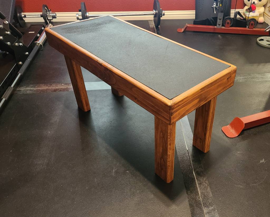
This entry of mine will not match the customary craftsmanship found in this community, but seeing as this was formerly a pile of miscellaneous, warped scrap 2x4 segments recovered from old pallets, I think I've made a reasonable show of things.

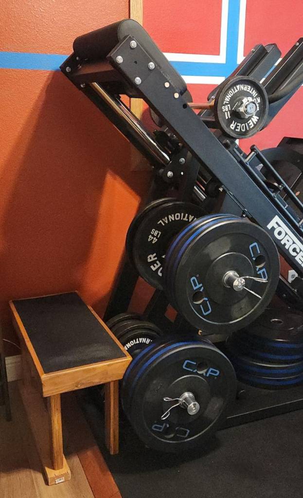
This bench is for my homegym, designed to be stood upon, which is why there's a rubber mat inlaid on the surface, a leftover of the gym floor. My design criteria called for even the edge of the top surface to support weight, so the main "box" of the bench uses 2x4 segments mitered (badly) together at 45 degrees, held together with wood glue.

I then routed the inner edge to support a 1/2" plywood sheet, which is screwed into the box. And then the rubber mat is glued down to the sheet, so there are no visible screws.

Finally, the legs are also 2x4 segments, cut so the bench sits 43 cm (~17 inch) from the floor; this is only coincidentally similar to the IPF weightlifting bench standards. I used screws instead of glue, just in case the legs needed to be shortened later.

All edges were rounded over with a 1/2" bit, as the bench is expected to be picked up and moved frequently. And everything stained in cherry and clear-coated.

Some of the annoyances from using scrap included:

  • Stripping old paint off. Awful chemicals, awful scrubbing, awful disposal.
  • Sanding away twists along the 2x4 segments
  • Filling nail holes or arranging them so they don't draw attention
  • My lack of experience with clamping and gluing wood that's not dimensionally consistent

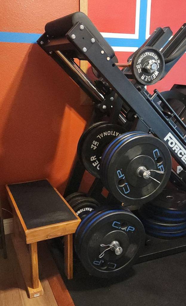
wood bench beside a leg press

If I were to do this again, I'd figure out a way to reduce the amount of routing needed for the inner edge, since I essentially removed 0.75 inch by 1.5 inch of material all around the edge. This took forever, and perhaps a CNC machine would have simplified things, in addition to squaring and planing the surfaces before mitering.

77
submitted 3 months ago* (last edited 3 months ago) by [email protected] to c/[email protected]
 

This entry of mine will not match the customary craftsmanship found in this community, but seeing as this was formerly a pile of miscellaneous, warped scrap 2x4 segments recovered from old pallets, I think I've made a reasonable show of things.

This bench is for my homegym, designed to be stood upon, which is why there's a rubber mat inlaid on the surface, a leftover of the gym floor. My design criteria called for even the edge of the top surface to support weight, so the main "box" of the bench uses 2x4 segments mitered (badly) together at 45 degrees, held together with wood glue.

I then routed the inner edge to support a 1/2" plywood sheet, which is screwed into the box. And then the rubber mat is glued down to the sheet, so there are no visible screws.

Finally, the legs are also 2x4 segments, cut so the bench sits 43 cm (~17 inch) from the floor; this is only coincidentally similar to the IPF weightlifting bench standards. I used screws instead of glue, just in case the legs needed to be shortened later.

All edges were rounded over with a 1/2" bit, as the bench is expected to be picked up and moved frequently. And everything stained in cherry and clear-coated.

Some of the annoyances from using scrap included:

  • Stripping old paint off. Awful chemicals, awful scrubbing, awful disposal.
  • Sanding away twists along the 2x4 segments
  • Filling nail holes or arranging them so they don't draw attention
  • My lack of experience with clamping and gluing wood that's not dimensionally consistent

wood bench beside a leg press

If I were to do this again, I'd figure out a way to reduce the amount of routing needed for the inner edge, since I essentially removed 0.75 inch by 1.5 inch of material all around the edge. This took forever, and perhaps a CNC machine would have simplified things, in addition to squaring and planing the surfaces before mitering.


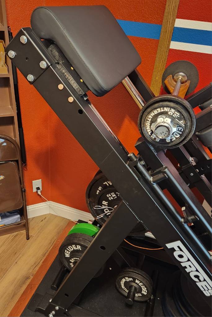
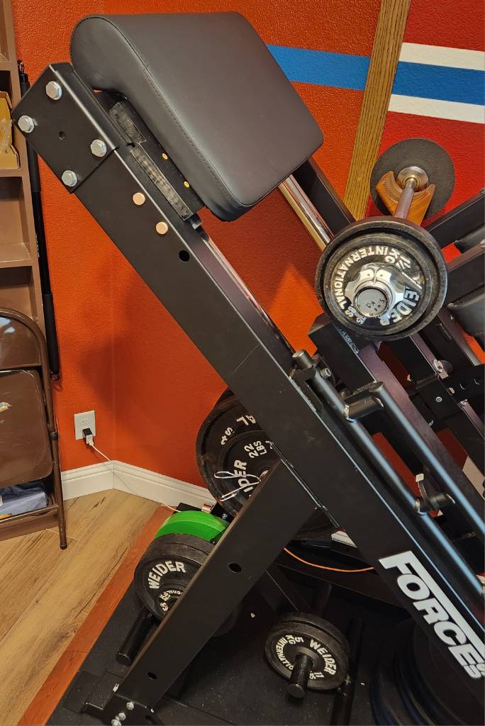
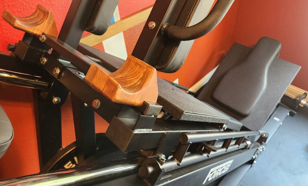
The idea for this strange combination of arm day and leg day came from realizing that my existing leg press and many commercial preacher curl benches both share a 45 degree angle. So in the interest of consolidating floor space, I decided to build a preacher curl bench attachment for my Force USA machine.

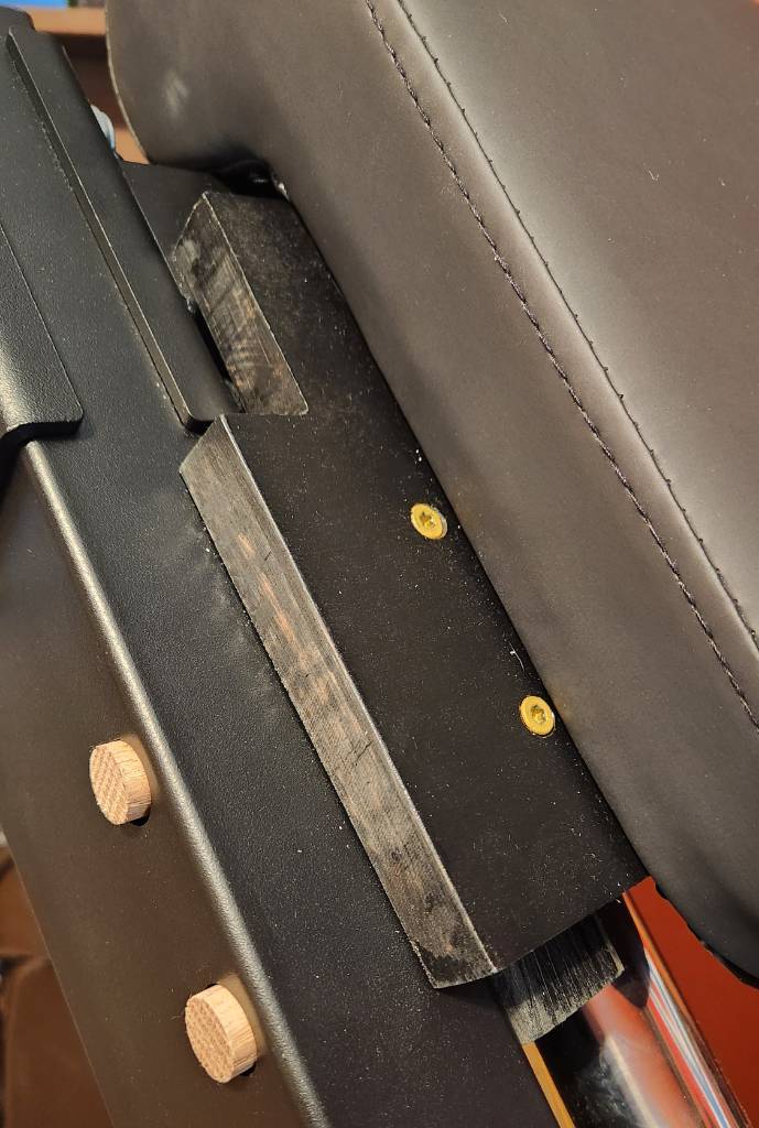
Just like with stripping down the machine to fit against a wall, the goal is to build something which is removable, if I wanted to restore the machine back to factory condition. Conveniently, at the top end of the machine, there are three 11/16 inch (17 mm) holes on each side, meant for resistance band pegs. Likewise, between the frame and the chrome running surface is approximately 1.5" (38 mm).

Thus, it made the most sense to cut pieces of 2x4 lumber (actual size: 1.5x3.5 inch) that will sit within the frame, secured by two snug-fitting 5/8 inch (16 mm) wood dowels going through the top-most band peg holes. These side-pieces are held captive by the dowels, although the pieces can still slide inward of the frame, falling away from the peg holes. They're also not really weight-bearing. But they do provide a foundation to build upon.

To form a sturdy and flat base, I then cut some scrap 3/4 inch (19 mm) board that spans the width of the frame, and screwed it down onto the side-pieces using Torx deck screws, notched to avoid protrusions on the frame's top surface. This makes the board weight-bearing, since it rests flat upon the frame; the side-pieces prevent the board from sliding down. And by fixing the width of the side-pieces, the pieces can no longer fall away from the peg holes.

close up of preacher curl attachment on the leg press

Finally, any preacher curl bench requires a pad. For this, I simply went online and found what existing machines used. Having had a good experience with the parts department at Body Solid for my functional trainer, I looked at their GPCA1 preacher curl station, whose detailed PDF schematics showed a pad that is 600 mm wide, which is perfect for my use!

After $40 + $20 shipping, the pad arrived and I was able to measure the exact distance between its two bottom mounting holes to drill through the board. Once again, Body Solid's documentation described the exact 5/16" wide, 1" long bolts that I would need to mount the pad.

The final result isn't my nicest wood project -- to the point that I just stained it (badly) in black -- but it may have been one of the cheapest so far, using nearly entirely scrap materials except for the pad itself and the bolts. It also wasn't terribly complex and didn't require fairly high precision, unlike the short barbell project.

The whole premise of this attachment is that as an average height American (5 ft 9 inch; 175 cm), my range of motion for the leg press and hack squat simply won't ever push the carriage into the upper part of the frame. So it's free real estate.

preacher curl pad attached to the top of a 45 degree leg press

But wait: how am I going to use this? The pad is 5.5 ft (167 cm) above the floor. I'd have to be over 7 ft tall (2.2 m) to drape my arms over it. The answer to that will be its own future post.


cross-posted from: https://sh.itjust.works/post/20965205

This is the story of how I turned a 15" Titan adjustable dumbbell to be 80 cm (31.5 inch) long. Why? Because I have a space-constrained home gym but still wanted a leg press, and so I had to remove its original barbell.

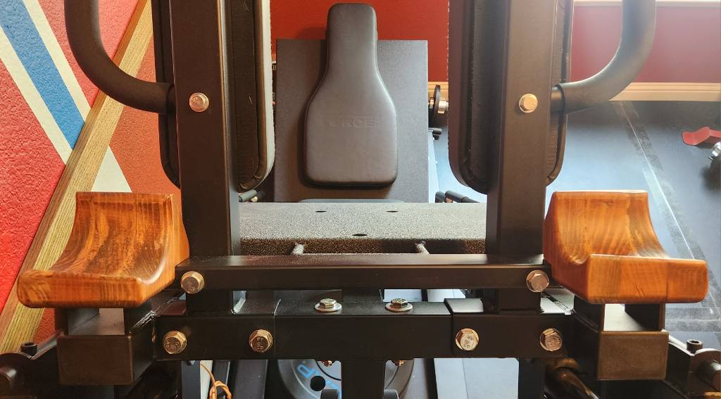
In its place, I built a pair of wood mounts for a normal barbell to rest upon, covered in that earlier post. However, since this machine is wall-adjacent, such a barbell would have to fit inside the width of the leg press, so about 80 cm. But must also be wider than the spacing from outside-edge to outside-edge of the wood mounts, which is 60 cm.

wooden mounts where a leg press barbell would be

Such a short barbell -- or long dumbbell -- does not readily exist commercially, with the narrowest one I've seen being 48 inch barbells, which are still too wide. So I decided to build my own, using my spare Titan dumbbell as the base.

To start, the Titan dumbbells are excellent in this capacity, as the shaft diameter is 28 mm -- not 32 mm as the website would indicate -- which is a common diameter, if I am to cut short a cheap barbell to replace this dumbbell's shaft.

In keeping with my preexisting frugality, I purchased a cheap 1-inch barbell, hoping that it adopts the Olympic 28 mm shaft diameter, and not the 29 mm deadlift bar shaft diameter, as the Titan collars have small clearances. Matching neither, I find that this bar is closer to 23 mm, which although will fit into the existing collars, poses its own issues.

Nevertheless, this 7 ft barbell can conveniently be cut in half to yield two 42 inch segments. And then the included bar stops can be loped off, and then the length further refined to 77 cm, thus hiding the marks from the bar stop within the Titan collars, and also centering the (meh) knurling from the cheap bar.

But perhaps a picture will be more explanatory. Here, the original collar is dismantled at the top, showing the original shaft with a groove cut into it, about 1/4-inch from the end. Into that groove would fit two half-rings with an inner diameter of 20.4 mm and an outer diameter of 40 mm. In fact, all the parts inside the collar use 40 mm outer diameter, except the spacer cylinder, which is smaller at 37 mm. All of these parts are held captive within the collar using the C-ring and the geometry of the collar itself.

To deal with the difference between the collar expecting 28 mm, and the cheap bar's 23 cm, I designed an ABS 3d printed part in FreeCAD to act as a bushing, upon which the original Titan brass bushing will ride upon. This ABS bushing is held captive by way of its center bulge, which fits within the dead space inside the collar.

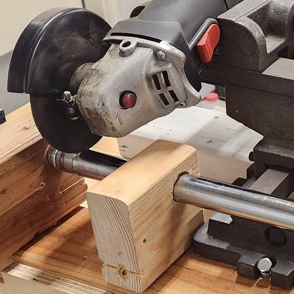
As for how I cut the groove into the end of the new shaft, I still don't own a lathe. So the next best is to mount an angle grinder onto a "cross slide vise" taken from a drill press, with the shaft secured in a wooden jig to only allow axial rotation manually. The vise allows precision control for the cutting wheel's depth, with me pausing frequently to measure how close the groove is to the desired 20.4 mm inner diameter. This is.... not a quick nor precise process. But it definitely works.

After reassembling both collars onto the new shaft and lubricating with white lithium, the final result is a long dumbbell (or short barbell) with Titan's 3.5 inch collars on the end, with 63 cm of shaft exposed and 80 cm from end to end. The ABS bushing is remarkably smooth against the brass bushing, after some sanding with 180 grit. The whole dumbbell weights 5.48 kg empty.

Here is the comparison with the stock Titan dumbbell. It's pretty amazing how the knurling conveniently lined up. It fits well onto the wood mounts of the leg press.

Don't ever talk to me or my son ever again

But why would I do all this just to add a weirdly long 3.5-inch collar dumbbell to a leg press, when it already can accept weights underneath the carriage? I will answer that in a follow-up post.


As is their custom, FortNine delivers a two-wheeler review in the most cinematic way possible, along with a dose of British sitcom humor.

I'm not sure I'd ever buy one, but I'd definitely borrow it from a friend haha. I've said before that I like seeing what novel ideas people will build atop two wheels, and this certainly is very unique.


The title describes the gist of things. In 18 months of owning my Bikonit MD750, I've traveled over 2100 km (1300 miles) in day, night, and rain; swapped out four sets of tires trying to lower the rolling resistance; built my own new set of 29" wheels with ebike-speed rated tires; and have taken it on mixed-mode adventures by using light-rail as my range extender.

It's the latter where the weight is a small issue, as the light rail train has three stairsteps onboard, which I have to carry the bike up and onto. 43 kg is kinda a lot, although that does include all the things I will need for a day out. I can pursue getting stronger to lift it more easily, or convincing the transit department to acquire low-floor trains, but I'd like to know my options:

What are some Class 3, mid-drive ebikes currently available in the USA, that weigh less than 43 kg (95 lbs)? Ideally, less than 25 kg (55 lbs) too, as that's the most common weight restriction for buses. I want to see what y'all can recommend, irrespective of price or range or other considerations.

I'm not likely to terminate my investment in this current ebike, as it's provided sterling service thus far. But I wonder if maybe what I have has already been outmoded by the latest developments in this ever-changing slice of the mobility space.

TY in advance!


One thing I've always wanted for my space-constrained homegym is a leg press. But even the most compact leg presses occupy a lot of space lengthwise and width-wide. I had my eye on the Force USA 45 degree leg press/hack squat combo machine, because it has so much capacity for me to grow into. So I picked one up and modified it so it can be placed up against the wall.

The primary issue is the barbell that attaches to the carriage (the part that moves up and down). This barbell extends about 45 cm (18 inch) beyond the left and right sides of the machine, taking up stationary space as well as dynamic space when the carriage is in motion. Eliminating that barbell would reduce the width requirement from the bare minimum of 162 cm to 80 cm, assuming the weight storage pegs are also removed.

But of course, the barbell is how the leg press is loaded, with 34 cm on each end for Olympic-spec plates. It also provides some structural stability for the hack squat shoulder pads, where they attach to the carriage. However, dangling underneath the carriage is a much-smaller space for loading plates, with 20 cm on left/right for plates.

Force USA leg press under-carriage plate holder

As an aside, this is a fairly substantial machine that arrived on a pallet, taking a few hours to assemble. The build quality is exemplary, and everything about it evinces durability and stability.

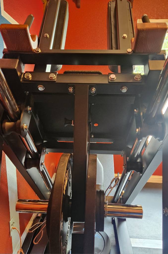
My approach was to remove the original barbell, loading only the under-carriage bar. To retain structure, I cut 1"x2" rectangular steel tube to the width of the carriage (59 cm), capped the ends, and drilled holes to reuse the same bolts as the original barbell. The reason for 1"x2" is because the backrest for the hack squat requires clearance; the stock barbell solved this by bending around that area, whereas 1x2 just barely clears the backrest, and that's good enough for me.

top-down view of replacement steel tube and mounts

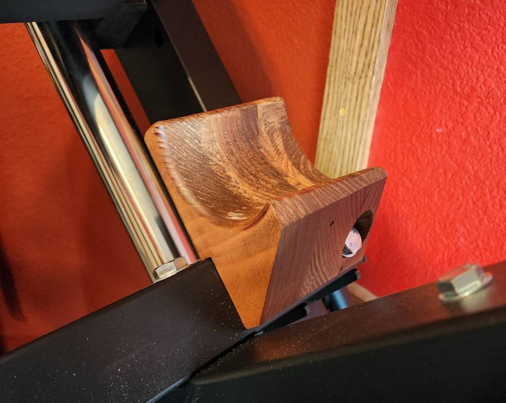
Later, I added a pair of wooden mounts where a conventional barbell can be rested. This is not my proudest woodworking achievement, but it's certainly the most unconventional. Each mount is made from three layers of reclaimed 2x6 lumber (from a bed frame) glued together, then a 3.5-inch diameter hole bored through axially, then sanded, stained in cherry, and finished with Polycrylic clear coat for durability. I'll explain the point of these mounts in a different post.

left-side wooden mount on the leg press

The result of all this is a leg press that needs only about 1 meter by 2.4 meter (39" by 96") of floor space, and that's including weight storage pegs on the side away from the wall, plus space to swing the safety stopper bars in/out of place. And everything can be reverted back to the factory configuration.

The caveat is that I'm consigned to the 40 cm total barbell space under the carriage. To maximally load this machine, I would need to invest in thin iron plates, which apparently only are made to precise values, and are thus expensive. Examples: Rogue calibrated KG plates, and Hansu Power calibrated plates, both of which are 22.5 mm wide for 20 kg plates. Sixteen such plates would make 320 kg (700 lbs), and I'd be thrilled if I could get there one day. The tradeoff is reasonable to me, minimizing floor space today in exchange for requiring expensive plates in the future, until I upsize my space.


cross-posted from: https://sh.itjust.works/post/20133956

With the exception of the weight stack for my functional trainer and its change plates, I wanted all my subsequent equipment to be metric. To that end, I saw some cheap 45 lbs CAP bumper plates, and figured that I could make them into metric with not too much effort.

Some rough math prior to purchasing suggested that these plates -- with a width of 68 mm -- could be slimmed down from 20.4 kg (45 lbs) to nearly 20.0 kg, by boring two 2" holes (51 mm). To keep balance, the holes should be on on diametrically opposite ends. And should be neither too close to the edge, nor too close to the center, since the plate still needs to absorb a drop without deforming. That the bored holes are 51 mm is a fantastic happenstance, nearly identical to the center hole for Olympic-spec plates.

Examining each plate before drilling, I found that the silkscreen letter A in "CAP" is well-centered diametrically, although it doesn't line up with the matching logo on the back side. Also, since these are cheap CAP plates, the initial weight tolerances are pretty poor. 45 lbs should be 20.41 kg (2 sig figs), but my first four plates registered at 20.58, 20.51, 20.64, 20.56. That's nearly an extra half pound!

To drill the holes perfectly plumb, I did the work on a drill press using a 2-inch hole saw. Because the saw wasn't deep enough to go through the full width in one pass, I started with a 1/4-inch (6 mm) pilot hole straight through the tip of the letter A in "CAP". Then I drilled from both sides with the hole saw until a ~200 gram rubber core fell out. Repeat for the second bore.

To finish, I took some sandpaper to remove the old "45 lbs" markings, then used my label maker to affix new values. All plates are still high, but ranged from 20.030 kg to 20.105 kg. Not too shabby, I think.

In a happy coincidence, the position of these bored holes is perfect for one's thumbs when grasping the plate like a steering wheel, making it easier to pick up when laid flat on the floor. I also added a strip of blue electrical tape around the perimeter to make it easy to identify these as 20 kg.

In the end, I got the cheap metric plates I wanted, and it came with a usability improvement as well. I've not dropped these yet, so time will tell how they hold up.

view more: next ›